Windlass
Chain box easy gets 90' 5/16 G40 and have about 10" above for windlass to have some drop
Dry fit of windlass mount
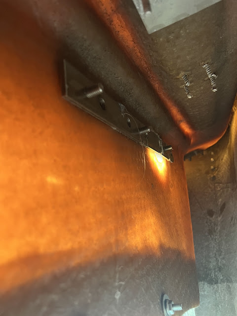
Mount installed on 6 bolts 3/8. From inside I put 1/4" SS backing plates with threaded holes to make work easier due to back side of the chain locker is a very hard to reach.
All sealed with butyl tape. Holes in original chain locker box i made right to size of the bolts and countersinked. holes in windlass mount are oversized to let butil to come around the bolt. during installation I put excessive amount of butyl on the bolt neck and then compressed into the hole with wide washers.
Mounting bolts from outside.
One of bolts is on the edge old of closed Hole no issues. At that place mount has only force down working load.
And from inside. For the back plates i used old chainplates pieces. Plates are glued from inside to make work to screw bolts by one person easier (possible).
And other side
Recheck chain locker hatch cut template
Hatch cut and fitted to place. Next is re-glass the core was opened during cutting, repair cracked cross member on the back side. Likely will cut hatch on two parts, one - front part, will be mounted on screws, and aft part will be a hatch. For some strange reason chain locker hatch has no latch at all.. I am going to add one. Probably will leave handle too.
Windlass installed on the place. I did 3 test runs - put anchor and all 90' chain down in 50' depth (i understand that 30' was lay on the anchor on the bottom) but it sound ok for today test. I pay out whole chain and pull it up. So far all works well, bucket takes all chain in w/o my intrusion. One time I unintentionally "caught" dock structure and try to lift dock. Without willing I checked windlass on full load. Windlass, mount and roller survived ;-)
Final view. Looks like it was a part of original design.
Electric side of windlass.
I decided to use dedicated battery for the windlass.
Why?
- I have nice 55AH AGM battery on hands.
- 15-20' shorter wires between battery and windlass.
- Even if I deplete it completely I will be able to start engine and have energy for house.
- I always may use other energy sources to recharge windlass battery.
- Always nice to have spare battery on board.
So, windlass electrical system looks like: Battery - 50A breaker (on positive) - Shunt (battery monitor, on negative), Winch solenoid relay (4 pole relay). Solenoid controlled by remote control block (12 Custom Wireless Remote Control Switch 2 CH 433Mhz ). To "Marinate module I Mounted it in hermetically closed box and covered electronic board with polyurethane conformal coating.
Control electronics and solenoid installed on mount block. Test before installation.
Control electronics installed to place. Back plate glued to hull with Epoxy and 404 filler.
Battery will be installed on starboard side under v-berth. Mounting shelf template made. Will install it next week. For now, battery just lay down on the bottom. Breaker will be mounted inside the cabinet.
Also plan to use it as battery switch.
Battery charger 12 AWG cable routed to the battery. Additional fuse installed on positive side next to the battery.
Temporary "Dry fit" electrical check.


Comments
Post a Comment