Navigation electronics
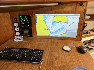
Couple pictures for reference:
Nav station deck.
Front side of the secondary switch panel.
Start point
Work was done today
- Open-plotter electronics BOX installation.
- Adding connector in between the switch panel and rest of the system.
- Organizing all wires in between Switch panel and fuse box.
- Terminal Block installed to organize power connections to peripheral devices.
- Finished wiring to tanks gauges (2x water tanks and fuel tank).
- Connected coolant temperature sensors to engine monitor module.
- Installed drive shaft packing box temperature sensor.
- Connected engine monitor module to ground and alternator.
Little more details about several things:
Open-plotter electronics BOX installation on the boat
Ip68 plastic enclosure to protect most vulnerable Openplotter electronics from elements contains baseboard, Raspberry pi and HDMI display interfaces splitter. All connections done with IP68 connectors.
Baseboard, kind of RPi HAT board but big one and RPi mounted on it vs HAT board usially mounted on Raspberry Pi.
Baseboard provides protection for RPi interfaces to survive in hard marine environment and in case of mild atmospheric electricity discharge.
Note: Actually almost impossible to make direct thunderbolt protection for working electronics - cheaper to have spare set of electronics in Faraday cage box.
- Raspberry pi 5 - 8GB installed and mechanically secured, 40 pin connector.
- 2x USB 2.0 1x4 hubs, makes 8 high protected USB 2.0 ports with 2A power capacity from 2 USB 2.0 RPi ports.
- Maiana AIS support port (direct RJ45 connection for Maiana)
- IMU
- Weather sensor (Pypilot project based), baseboard includes barometric pressure sensor and interface for direct connection of the Davis Anemometer)
- Two galvanic isolated NMEA0183 interfaces.
- dedicated interface for Pypilot motor controller.
- RPi power control
- Remote physical keyboard interface, will be used to control Pypilot. (Software is not ready yet)
- Two USB 2.0 power ports.
- HDMI splitter - provides copy of the navigation desk screen image to cockpit screen.
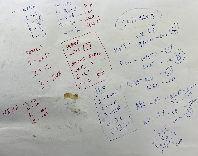
Adding connector in between the switch panel and rest of the system.
Connector pinout


Comments
Post a Comment