
Long story about hatches
I have decided to change original hatches with low profile aluminum profile type.
One guy on FB group recommended one particular type as direct fit. Maybe he has other IC34, and it was built differently, but I have got trapped.
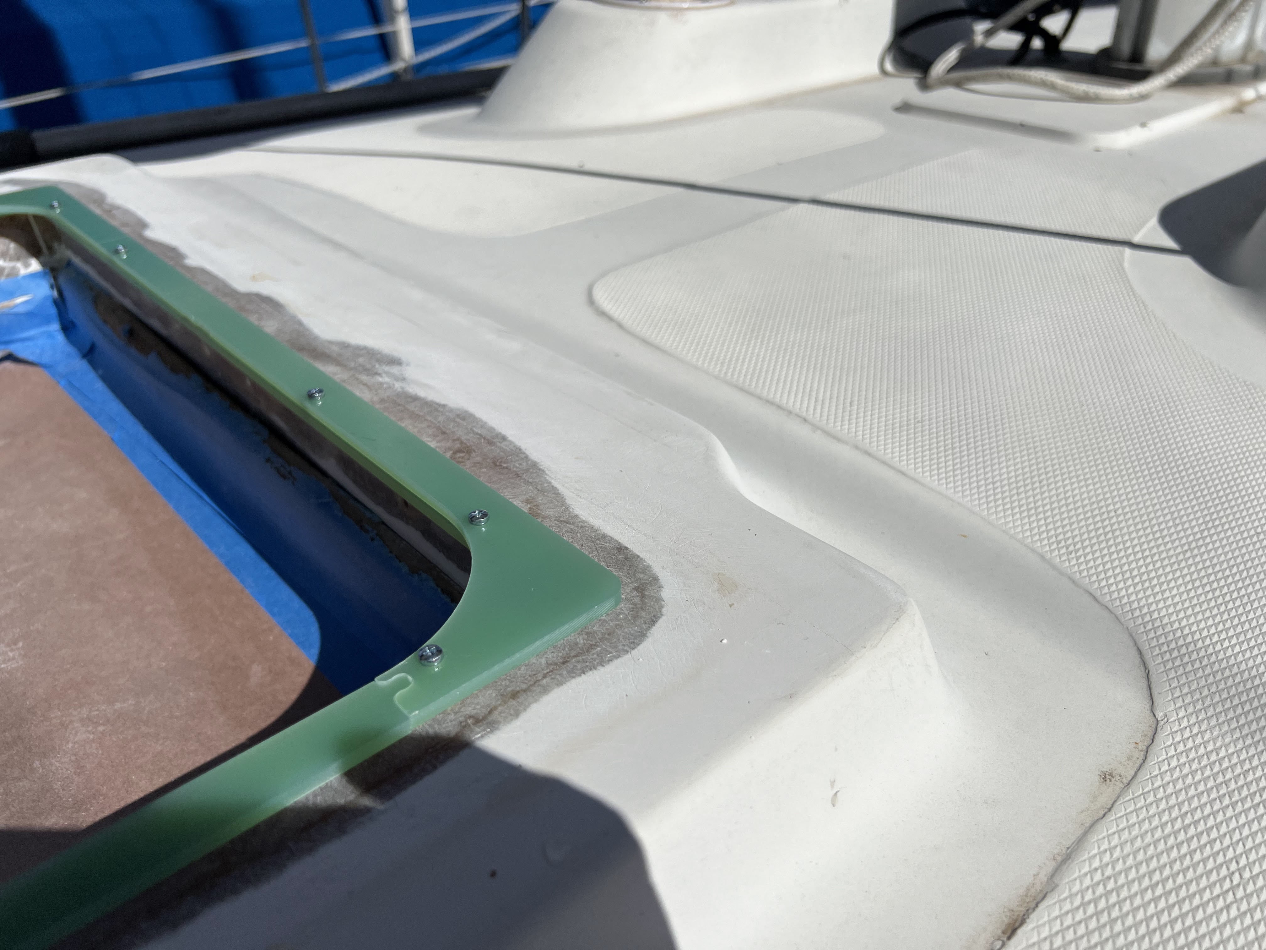
Unfortunately deck opening on MY boat was just square cut, so when I put brand new, sparkly hatches for dry fit I found corners of the hatch do not cover corners in the deck opening :-)
Also hatch appeared about 3/4 inch smaller then deck opening and mounting holes on the hatch appears EXACTLY on the deck frame edge.

Step 1 (Adapter frames)
I decided to make adapter frames covering corners and provides support for mounting screws.
After week thinking about solution I decided to make adapter from (G10) pre-manufactured fiberglass plate. Adapter thickness 16mm, it will have the lip to lay lay over the top of the deck, external adapter dimensions the same as original deck opening, internal dimensions and shape will fit hatch frame.
All good, but if I go straight and cut them from solid piece of (G10) FR4 sheet, one sheet 500x100x16mm thickness will cost me about 300$ for one hatch. It is prohibitively high price. And then throw away 80% of material.
I decided instead buy only two sheets 500x300x4 mm (total <$80) to build both adapters and, cut them in shape and laminate frames from 4 layers. Price difference - $80 vs $600. Easy to say, harder to implement :).
First layer is 5mm wider then deck opening (goes in little groove over the top of deck, routed by me), second layer exact width of openning ( goes inside) , third and forth layers just plates on sides do not over corners (just additional structural strength and capability to put screw from inside if I need.
Several hours of planning, design work, and play with my CNC.

Set of parts cut.
How I save material?


Left is parts for frame, right - leftovers. :-) Maybe i can use them as nice mixer sticks :-)
Construction:
Two top layers built from 4 pieces each - 2 pieces contains side and rounded corners, and 2 - just side pieces. To keep dimensions as needed pieces connected with jigsaw puzzle type ends.

First layer assembled

How parts connected horizontally.
Second layer assembled 90 degrees turned, so connections between layer parts are not overlapping.
To make better alignment between layers, and also provide support during machining small parts I added 4mm holes. During dryfit and lamination I used M4 screws to compress layers together.


Pack is assembled for dry fit.

One frame set is
ready for lamination. (here you can see how first layers are overlapping)


Frame is laminated.
After resin set, I unscrew nuts and cut of sticking thread from screws.
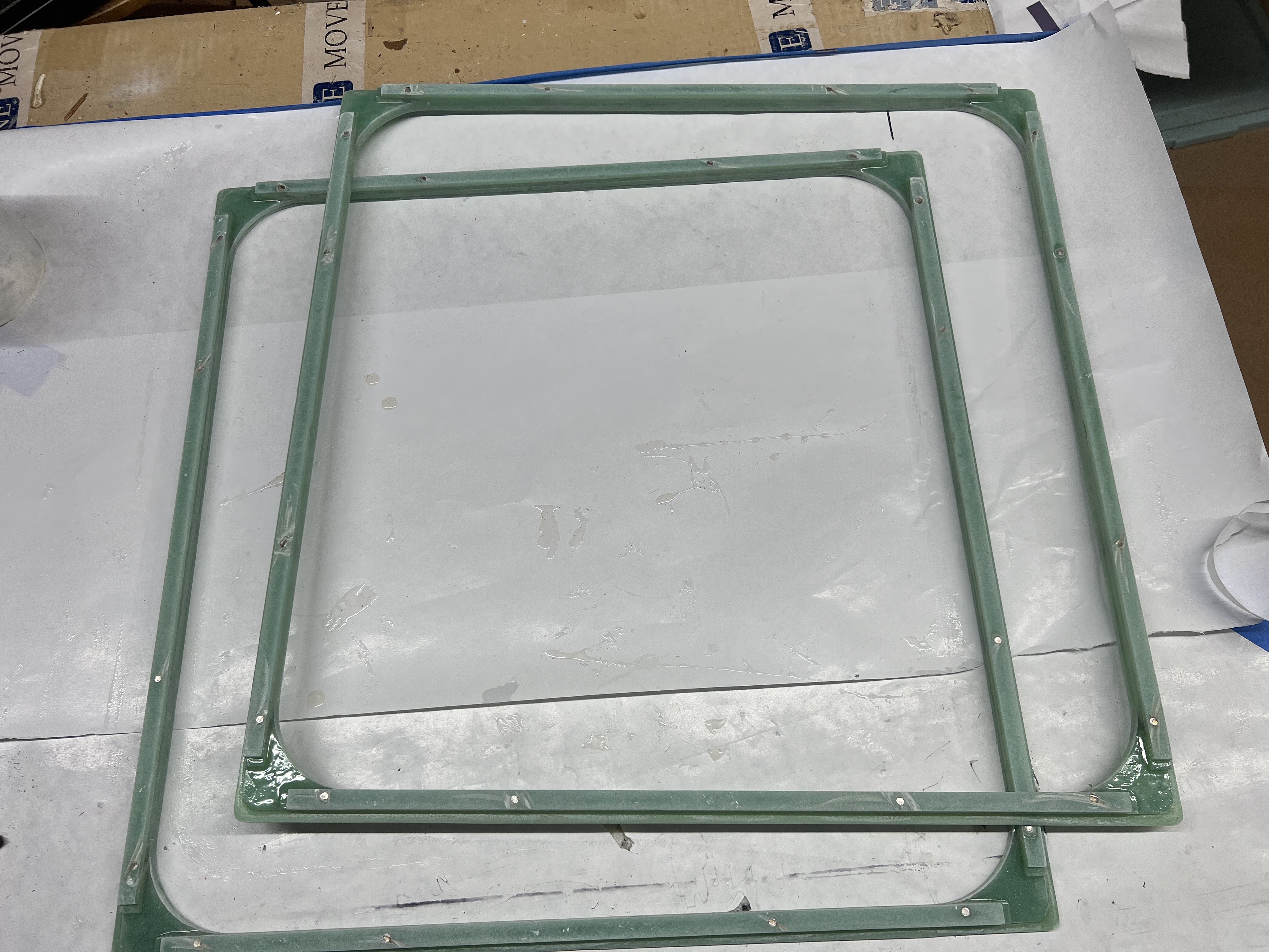
ADAPTER FRAMES ARE READY.
Step 2 (Prepare deck)
Now I need to take small amount from the corner edge of the deck opening to put adapter in flush with surface. also this operation is needed to fix uneven surface on the deck. (deck had about 3mm elevated corners)
I cut template from 3/4 inch MDF panel. unfortunately it did not fit my CNC as one piece and I had to cut 2 pieces and glue them together. Template is 1mm bigger than top layer of the adapter frame.

Edge routed (I used just hand router with template routing bit). REALLY DUSTY WORK. Worked in full body protection.

Step is routed. Template just screwed to deck in two corners to keep it not deformed and provide flat reference surface for routing the step.
Found some voids in original lamination, I filled them with thickened epoxy.

One more dry-fit.
By the way, here you can see I removed all gelcoat from the deck surface in hatch "elevation". I tried to sand it out, and in some places gelcoat was 3-4mm thick and it took a lot of time and effort. I do not know how professionals pill gelcoat, but I found small hand router with 3/4 wood routing bit like below works great, just set it 0.5mm or about sticking out of router. It is MUCH easier than sanding. I cleaned all surface less than a minute. Sure you have to be VERY careful and stop routing surface as soon as it start showing fiberglass, then finish work with orbital sender.


Step 3 (Epoxying frames to place)
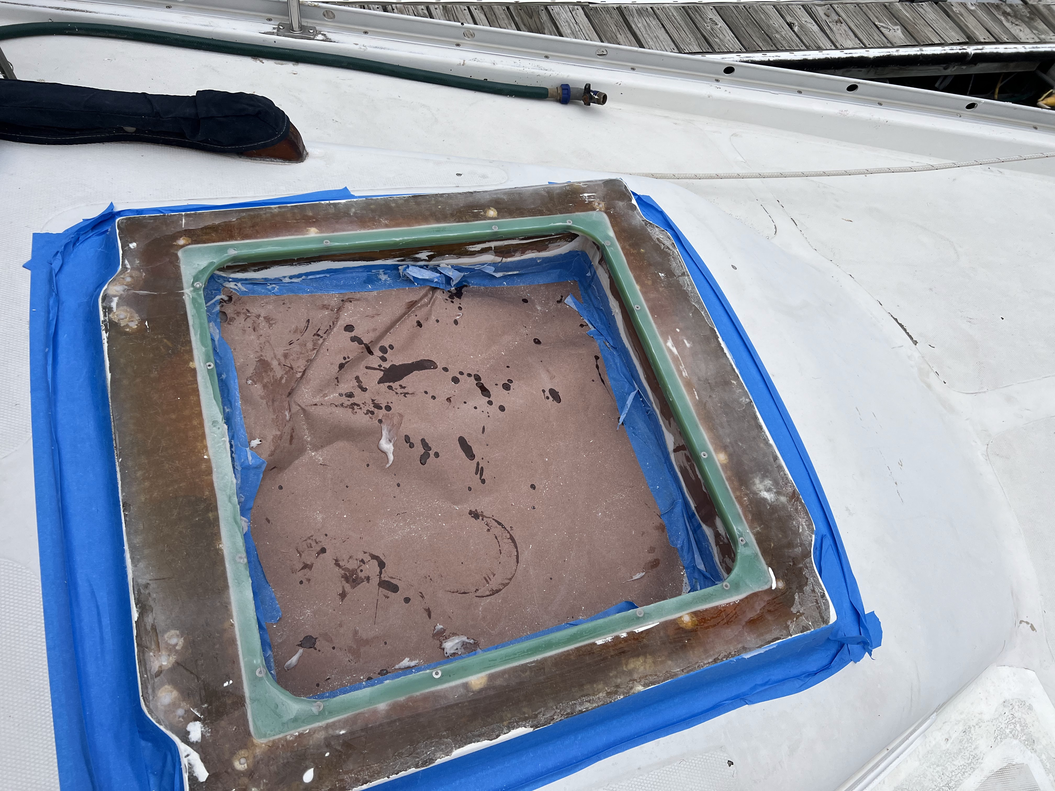
Frame set on thickened epoxy
Step 4 (Glass over to make solid surface)

I glassed whole surface over with layer of 1708 glass mat.
Step 5 (Make flat base surface)

After "mold" removed. Yes , surface is not flat and has air bobbles and paper wrinkles, but it is good flat reference plane.
Step 6 (Surface fairing)

Step 7, 8 (Priming-sanding-priming-sanding)


Step 9, 10 (Painting)

No picture before installation, sorry. Looks the same but all white.
Step 11 (Hatches installation)
Several sub-steps:
11.1 Dry fit frames
11.2 Center pre-drill mount holes positions with drill bit size of holes in the hatch.
11.3 Remove hatch and drill holes for thread tapping 10-24 machine screw thread
11.4 Tap thread in the holes
11.5 Clean surfaces with 50% diluted propranolol
11.6 Apply butil tape to hatches
11.7 Put hatches in openings and screw them to frames.
11.8 Vacuum all dust and remove brown paper plugs.
11.9 Peel protective film from hatches.
11.10. collect all tools, trash e.t.c. and take pictures.


Small things
After slip and almost fall inside the cabin on steps in companion way I added nonskid stickers to refinished steps. This way is better.

Nice work!
ReplyDelete